

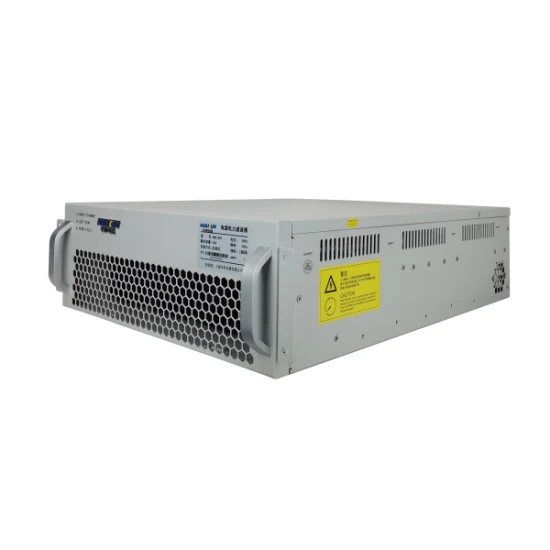
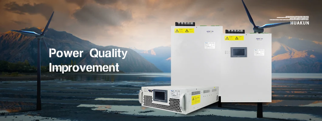
Static Var Compensator for Power Fault Shanghai Svg
Static Var Generator (SVG) is a product aimed for Power Factor Correction, Voltage Regulation along with Three-phase Bal;
Basic Info
| Model NO. | SVG035 |
| Application Range | Power Factor Correction |
| Shell Material | Aluminum-Zinc Coated Case |
| Shell Protection Grade | IP30 |
| Brand | Huakun |
| Mounting Type | Wall Mounted/Rack Mounted |
| Power Grid Structure | 3p3w/3p4w |
| Noise Level | <65dB |
| Harmonic Compensation Range | 2~50th Harmonic Order |
| Harmonic Compensation Efficienc | > 97% |
| Usage | Harmonic Correciton ,Reactive Var Compensation |
| Transport Package | Wooden Box |
| Specification | 682*567*277cm |
| Trademark | Huakun |
| Origin | Shanghai, China |
| HS Code | 8543709990 |
| Production Capacity | 20000PCS/Year |
Product Description


| System parameters | |
| Rated input wire voltage | 3 8 0 V(-1 5%~+2 0%) |
| Grid frequency | 5 0 / 6 0 H z ( r a n g e : 4 5 H z~6 2 H z) |
| Number of parallel machines | 1 ~ 1 0 s e t s |
| Overall efficiency | ≥9 7% |
| Grid structure | T h r e e - p h a s e t h r e e - w i r e / t h r e e - p h a s e f o u r - w i r e |
| Current transformer | 1 5 0/5~1 0 0 0 0/5 |
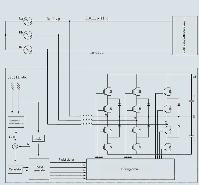
| Circuit topology | T r i - l e v e l |
| P e r f o r m a n c e i n d e x | |
| Response time | <1 5 m s |
| Scope of compensation | F r o m - 1 t o 1 , c a p a c i t i v e a n d i n d u c t i v e c o n t i n u i t y i s a d j u s t a b l e |
| Cooling mode | I n t e l l i g e n t a i r c o o l i n g |
| Noise index | <5 6 d B |
You may also like
Send inquiry
Send now